Country Style Cabinets With a Furniture Flair – Part 1
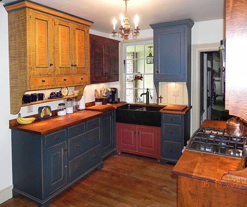
Jeremy is interested in and wanting to evaluate CabWriter. He forwarded to Greg the picture above and said:
“The stuff I am wanting it to do are not standard cabinets for the most part. They are early American/ county cabinets with furniture styles scribed to the floor and I would like to see what the different options for construction of the boxes in such I can do.”
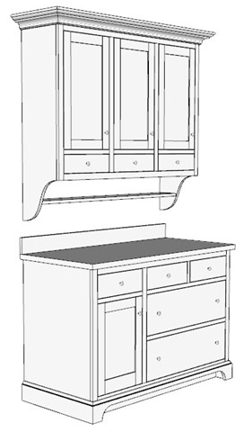
We sometimes think of cabinetmaking as box building from designs that lack ostentatious styles. But we shouldn’t. There is no reason kitchen cabinets, vanities, offices or closets need to be modest or plain. Fortunately, CabWriter sits on top of SketchUp, hence all of SketchUp’s native capabilities are available to the cabinetmaker and architect. In this post I will demonstrate how I created two of Jeremy’s cabinets; one base and one upper. Jeremy’s picture above is rather dark in the front base area, but if you look hard the cabinets look like the SketchUp model drawn with CabWriter at right.
You will quickly notice several features that are not products of CabWriter: Crown molding, reverse ogee (the cyma recta S-shape) ends, counter top with back splash, base trim and drawer pulls. These features were all created with SketchUp native tools. But don’t panic! These items can be created once by the user, or downloaded from the internet, and stored in a library so they can be used over and over. No need to draw them for each use. In a future post I will show you how to do that, but today I want to focus on this design.
So that you can follow along with this post I have attached the completed SketchUp model and you can download it by clicking here. The base and upper cabinets used slightly different defaults, so as I discuss each one you might want to use the CabWriter “Retrieve Cabinet Defaults” tool to view the applicable CabWriter Settings tab.
The Base Cabinet
I began the base cabinet using the ‘Re-Load Factory Settings’ tool to establish a baseline set of defaults, then made changes to it. The base cabinet is a standard two box CabWriter cabinet. Though you may not see it in the picture at right above, the base cabinet is full face frame with bottom rail. The left box is a Standard Base w/ Drawer and the right box is a Drawer Bank Combo with three drawers specified. I changed the drawer heights in the Face Frame tab of CabWriter Settings to make the two drawers equal size in the drawer bank. Lastly, in the Drawers tab I selected “Slab” as the Drawer Face Style.
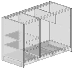
When creating the base cabinet I chose Left End Sheet and Right End Sheet for the end stiles. After drawing the base cabinet I made some changes using SketchUp tools. I extended the end sheets 3 1/2” at the bottom so that they were even with the bottom of the ladder base (1/2” off the floor). I deleted the end applied faces but kept the front applied face. I extended the front applied face to touch the end sheets and made the joint at the ends a butt joint. Then I moved the ladder bases end ribs and stretchers to sit up against the end sheets. I also lengthened the front and back ties to touch the end sheets. That completed all but the base trim, counter top and back splash components for the base cabinet. The base carcass and toe kick are shown at left in X-Ray view.
The Upper Cabinet – Divided Upper
The upper cabinet is a three box divided upper. The divided upper box is one I am coming to like more and more because of its flexibility. Again I established a baseline set of defaults using the ‘Re-Load Factory Settings’ tool. The first defaults change I made was to the Divider Upper on the Upper Cabinets tab; I changed its Cabinet Height to 36”. I then created the upper cabinet selecting Divided Upper and using a Shelf Offset of 5/8” and 6” for Position 1 with Fixed Shelf selected.
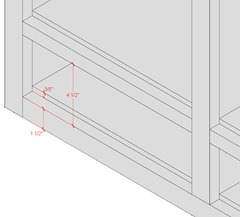
Because the bottom rail is 1 1/2” wide the 6” setting for Position 1 provides a 4 1/2” drawer front opening. That dimension is good for the drawer front, but it is not the opening as far as the drawer box is concerned. Upper cabinet bottoms are inset 1 1/8” which results in the bottom’s top being 3/8” above the top of the bottom rail, hence closing down the 4 1/2” opening to an effective 4 1/8” inch opening. From that you have to subtract 9/16” for drawer clearance on the bottom and 1/4” clearance on the top, leaving 3 5/16” for a maximum drawer height.
Looking at the smallest drawer height allowed in the factory settings default on the Drawers tab we see it is 4 1/4”. Therefore I needed to change it to 3 1/4” (1/16” less than 3 5/16”). After making this change, or any change in the CabWriter Settings dialog box, I must click the Update button to record the change. Now here is an important step. The change is recorded in CabWriter defaults, but not in the cabinet I just drew. I need to redraw this cabinet with the new settings before I can use the ‘Insert a Drawer’ or ‘Insert a Door’ tools. Failing to do so will result in error messages. Recovering from these errors adds more work. So think ahead and be sure of what your are trying to accomplish. Now I am ready to add the doors and drawers with the ‘Insert a Drawer’ and ‘Insert a Door’ tools.
Creating The Moldings
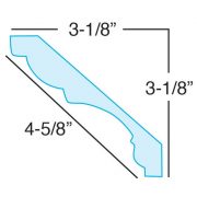
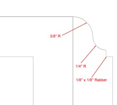
Creating the trim moldings is done entirely in SketchUp. The Crown Molding I created from a .jpg image found through an internet search. The .jpg is shown on the left above. I used the SketchUp Line, Scale, Bezier Curves and Follow-Me tools to trace and extrude it.The Base Trim, shown right, I created with the Line, Arc and Follow-Me tools, again creating an outline and extruding it. I highly recommend that when you do this sort of thing that you save them in a library for future use. They can be saved either as 2D cross sections, or as 3D components. I prefer the latter and will demonstrate how you can go about this in a future post.
The Video Tutorial
That’s enough background. This is Part 1 of a two part post. In this video I will draw the base cabinet and its trim. In Part 2 I will complete the upper cabinet. Now relax, kick off your shoes, put your feet up and enjoy some pop corn while I show you the entire process.

