CNC Integration
From Screen to Machine
CNC’s are increasingly common in today’s shop, large and small, due to the huge amount of efficiency they can bring to the process. However, for a CNC to be able to maximize your efficiency, you must have the proper software to drive it. There are hundreds, if not thousands, of software packages to choose from. Unfortunately, many of them are out of reach of the small shop due to their high cost, but there are some great options on the market for the smaller shop that won’t bust your budget.
Much of the cost of the higher end, CNC capable software packages are due to the fact that they try to do everything, including the nesting, G-code, and toolpath creation for the CNC that you’re going to use. This drives up the cost because there are literally thousands of machines on the market and it’s an expensive proposition to support that many machines. CabWriter’s philosophy is to do what we do best, fast and easy cabinet modeling, and let others do what they do best getting you from screen to machine in the fastest, most cost effective way.
DXF Export
Fortunately, CabWriter CNC provides a flexible method to integrate with your favorite Computer-Aided-Manufacturing (CAM) software which reads in the parts generated by CabWriter and creates the information necessary to drive your particular CNC. There are a number of great CAM software packages on the market, but only a few that are affordable, and capable. CabWriter facilitates the use of CAM software by exporting cabinet parts as a DXF file, which is a universal CAD file format describing a part’s geometry supported by nearly every software package currently on the market. Multiple export options are available; create one DXF file all the parts for each material type and thickness, export each part in it’s own DXF file, or export a DXF file for each optimized sheet.
Supported Machining Operations
One advantage of owning a CNC is because it gives you the flexibility to only drill holes where you need them. CabWriter Pro enables selective hole drilling for hinge plates, drawer slides, and shelf pin holes. By choosing the appropriate parameters, as shown on the right, you drill just the holes you need, where you need them, with the correct depth, diameter, and placement. With CabWriter CNC, the hole geometry will be exported to the DXF file on it’s own layer ready for tool path creation.
Starting with version 2.0, CabWriter Pro added support for new carcass construction methods such as captured backs, dados, rabbets, and qualified tenons along with standard butt joint construction. Using CabWriter CNC, all of the geometry necessary to cut the parts will be exported to the DXF File including all of the inside and outside perimeter cuts, pockets, and drill holes; each on their own layer. Any user defined circular or rectangular pockets or cutouts are also recognized by Cabwriter CNC and will be output to the DXF file.
Flexible, Custom DXF Layer Naming
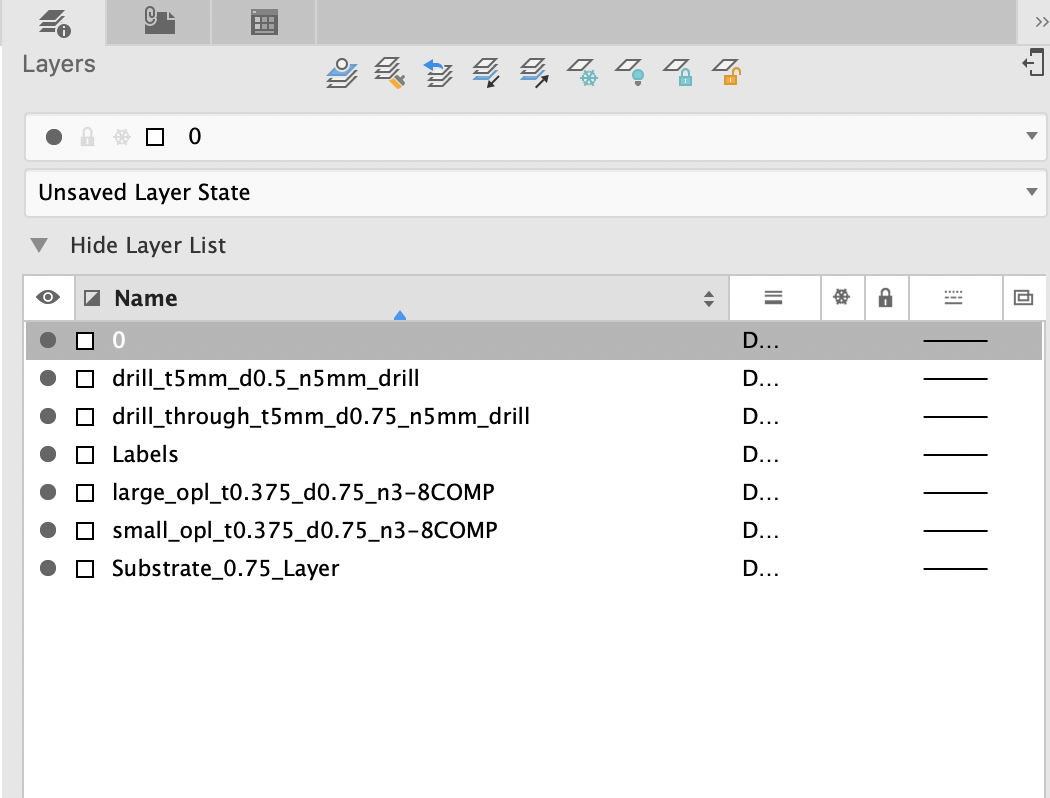
By default, CabWriter CNC creates a separate layer name in the DXF File for each unique machining operation. For example, all drill holes of the same diameter and depth, all pockets using the same tool diameter and depth, and all inside or outside perimeter cuts using the same tool diameter would each have their own individual layer to facilitate tool path creation.
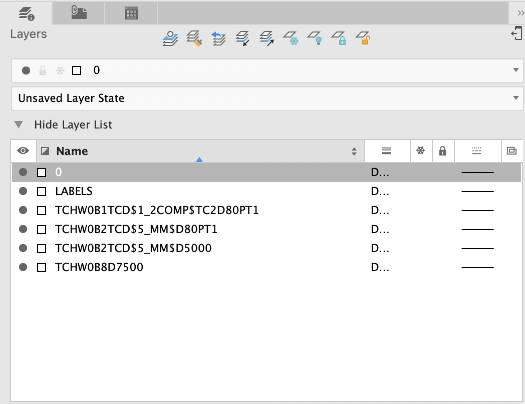
Beginning with CabWriter 2.0, users also have the option to generate custom layer names in the DXF export, as shown on the right. This is useful if your CAM software has the capability to machine directly from the information contained in the layer name which can be encoded with the machining operation type, tool name, tool diameter, and cutting depth. CabWriter will even allow you to encode layer names to be directly read by higher end CNC’s such as Biesse as shown at right.
New in CabWriter 5: Now includes support for CAM software that uses Z-Depth parameter in DXF files to specify tool path hole and pocket depth, more flexibility in layer naming for DXF drill layers, and layer naming in general
Label Printing
Print part labels using Avery 5163 (2″ x 4″) labels with up to 10 lines or Avery 5160 (1″ x 2 5/8″) labels with up to 5 lines. All parts on a specified scene or optimized sheet will have a label printed with ability to customize its contents.
CAM Software
One company that we highly recommend is Vectric which makes a range of affordable products that support a wide range of CNC’s. For cabinet work, Cut2D Pro, is an extremely capable choice at under $500 that will do everything needed for the average cabinetmaker. Scroll down to see how it works with CabWriter or watch our CabWriter overview video to see how easy it is to bring your design from “screen to machine” in no time!


Advanced Layer Naming Example
Biesse Style Layer Naming
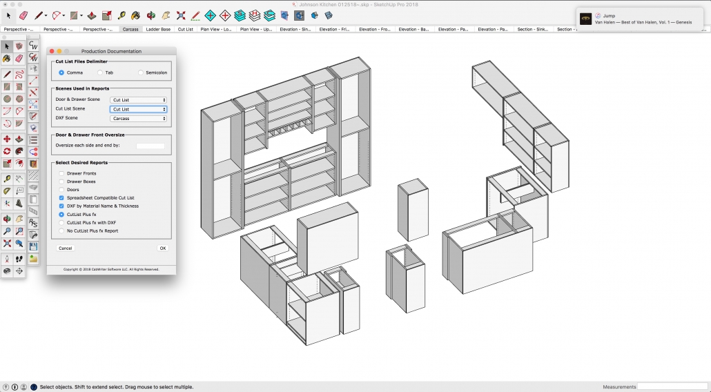
Choose File->CabWriter Production Documentation, choose a scene containing the parts to export, and check the DXF by Material Name and Thickness box”. In this case, we’re just exporting the the 1/2″ and 3/4″ pre-finished plywood carcass parts. A folder will be created in your SketchUp project folder that will contain a separate DXF file for each type of material containing all of the parts for that material type.
After starting Cut2D Pro, setup a new job. You’ll setup the parameters such as the plywood dimensions, thickness, and whether you’re using inches or mm.

Read in the vectors from your model. In this case, the vectors are the parts in the DXF file that CabWriter exported from the Sketchup model. One job consists of a single material type/thickness. In this case, we’re choosing to work with the 3/4″ pre-finished maple plywood.

All of the parts are now imported into the job. This view is only showing a few of the many parts, the rest are arranged in a long line going off to the right. All of the parts have been selected for the nesting operation which will place the parts as efficiently as possible on the fewest number of sheets.

Here’s the result of the nesting operation. All parts have been placed on 12 sheets of plywood.
Each unique geometry is put on a separate layer by CabWriter when it’s exported and is maintained through the entire nesting operation. The part perimeter, system holes, construction holes, and labels are each on their own layer because they will have different tool paths applied to them later. Note that there are two different layers for the part perimeters; one for Parts-Large and one for Parts-Small. Small parts can sometimes shift when being cut on a CNC, so CabWriter allows you to specify the threshold for the size of small vs. large parts so that you can optionally leave a skin or use tabs on the smaller parts when creating the tool path.

Next, create the tool paths for each type of geometry on all of the parts. Cut2D Pro has a great feature allowing you to use a number of Vectric supplied “gadgets”, which are really just utilities that ease the execution of complex functions. It can take a long time to create tool paths for all of the sheets because you have to manually choose each sheet and manually apply a tool path to each geometry. If you have a lot of sheets, this could take a considerable amount of time. Luckily, Vectric allows you to create templates to apply a tool path to a geometry based on a it’s layer name. Since CabWriter always puts the same geometry on the same layer name all the time (for example, 5 mm holes, not through the part on the “System Holes” layer), you can create a template once, then save it for use in the future. Lastly, you can download a Gadget that allows you to apply a template to all of your sheets automatically, saving quite a bit of time.

All of the created tool paths are shown for all sheets. Less than five minutes from CabWriter DXF export to tool path creation and downloading to your CNC!
